|
|
| |
|

|
|
|
|
| |
|
|
| |
 |
Latches and Flip-Flops
|
|
|
There are two types types of sequential circuits. |
| |
|
|
|
|
- Asynchronous Circuits.
- Synchronous Circuits.
|
| |
|
|
|
|
As seen in last section, Latches and Flip-flops are one and the same with a slight variation: Latches have level sensitive control signal input and Flip-flops have edge sensitive control signal input. Flip-flops and latches which use this control signals are called synchronous circuits. So if they don't use clock inputs, then they are called asynchronous circuits. |
| |
|
|
| |
 |
RS Latch
|
|
|
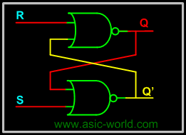
RS latch have two inputs, S and R. S is called set and R is called reset. The S input is used to produce HIGH on Q ( i.e. store binary 1 in flip-flop). The R input is used to produce LOW on Q (i.e. store binary 0 in flip-flop). Q' is Q complementary output, so it always holds the opposite value of Q. The output of the S-R latch depends on current as well as previous inputs or state, and its state (value stored) can change as soon as its inputs change. The circuit and the truth table of RS latch is shown below. (This circuit is as we saw in the last page, but arranged to look beautiful :-) ). |
| |
|
|
|
|
 |
| |
|
|
|
|
|
S
|
R
|
Q
|
Q+
|
|
0
|
0
|
0
|
0
|
|
0
|
0
|
1
|
1
|
|
0
|
1
|
X
|
0
|
|
1
|
0
|
X
|
1
|
|
1
|
1
|
X
|
0
|
|
| |
|
|
|
|
The operation has to be analyzed with the 4 inputs combinations together with the 2 possible previous states. |
| |
|
|
|
|
- When S = 0 and R = 0: If we assume Q = 1 and Q' = 0 as initial condition, then output Q after input is applied would be Q = (R + Q')' = 1 and Q' = (S + Q)' = 0. Assuming Q = 0 and Q' = 1 as initial condition, then output Q after the input applied would be Q = (R + Q')' = 0 and Q' = (S + Q)' = 1. So it is clear that when both S and R inputs are LOW, the output is retained as before the application of inputs. (i.e. there is no state change).
- When S = 1 and R = 0: If we assume Q = 1 and Q' = 0 as initial condition, then output Q after input is applied would be Q = (R + Q')' = 1 and Q' = (S + Q)' = 0. Assuming Q = 0 and Q' = 1 as initial condition, then output Q after the input applied would be Q = (R + Q')' = 1 and Q' = (S + Q)' = 0. So in simple words when S is HIGH and R is LOW, output Q is HIGH.
- When S = 0 and R = 1: If we assume Q = 1 and Q' = 0 as initial condition, then output Q after input is applied would be Q = (R + Q')' = 0 and Q' = (S + Q)' = 1. Assuming Q = 0 and Q' = 1 as initial condition, then output Q after the input applied would be Q = (R + Q')' = 0 and Q' = (S + Q)' = 1. So in simple words when S is LOW and R is HIGH, output Q is LOW.
- When S = 1 and R =1 : No matter what state Q and Q' are in, application of 1 at input of NOR gate always results in 0 at output of NOR gate, which results in both Q and Q' set to LOW (i.e. Q = Q'). LOW in both the outputs basically is wrong, so this case is invalid.
|
| |
|
|
|
|
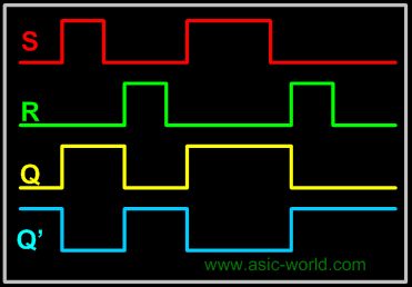
The waveform below shows the operation of NOR gates based RS Latch. |
| |
|
|
|
|
 |
| |
|
|
|
|
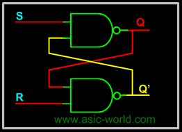
It is possible to construct the RS latch using NAND gates (of course as seen in Logic gates section). The only difference is that NAND is NOR gate dual form (Did I say that in Logic gates section?). So in this case the R = 0 and S = 0 case becomes the invalid case. The circuit and Truth table of RS latch using NAND is shown below. |
| |
|
|
|
|
 |
| |
|
|
|
|
|
S
|
R
|
Q
|
Q+
|
|
1
|
1
|
0
|
0
|
|
1
|
1
|
1
|
1
|
|
0
|
1
|
X
|
0
|
|
1
|
0
|
X
|
1
|
|
0
|
0
|
X
|
1
|
|
| |
|
|
|
|
If you look closely, there is no control signal (i.e. no clock and no enable), so this kind of latches or flip-flops are called asynchronous logic elements. Since all the sequential circuits are built around the RS latch, we will concentrate on synchronous circuits and not on asynchronous circuits. |
| |
|
|
| |
|
|
| |
|
|
|
|
|
| |
|
|
|
|
|

|

|

|
|

|
|
Copyright © 1998-2025 |
Deepak Kumar Tala - All rights reserved |
|
Do you have any Comment? mail me at:deepak@asic-world.com
|
|